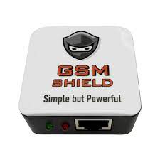
GSM Shield Box Setup
GSM Shield Box MTK Dongle Latest Setup Download Free
You download the latest setup of GSM Shield box from this page absolutely free. If you are wondering how to configure the GSM shield for Windows, this article will help you.
Read on to learn how to configure the GSM shield for Windows and program it. You can also use a SIM from a different network provider. After you have configured the GSM shield, you can test it to see if it works. The following steps will walk you through the process step-by-step. Once you have completed these steps, you should be able to use your device.
Configuring the GSM Shield for Windows
You can use the GSM Shield Box Setup for Windows with a PC with an Ethernet port. Once you have installed the GSM shield software, you can configure its settings through the GUI. You will find several AT commands in the GUI.
These commands let you change the baud rate and receive and send messages. The GSM Shield Box Setup for Windows is easy to use, and it only requires a 5V external power source.
Also, DownloadUFS Turbo Box Setup
The first step is to turn on the GSM shield. To do this, you need to press the power button for two seconds. Once the shield finds a network, the LED will blink every 800 ms. It will then turn off automatically. Once the GSM shield has been configured, you can make calls.
To make a call, type the target number into the target phone number field without any quotes. If the number is not intelligent, the SIM shield will fail to process the call. Moreover, you may have to input the wrong command format.
After you have successfully configured your GSM shield for Windows, the next step is to set the power source. You can use a standard USB power supply.
Make sure the USB power supply is 5V or higher. Also, press the power key on the GSM shield for Windows to turn it on. Wait about eight minutes before you can turn on the device. When you do so, the LED will blink every 800 ms until the network is found.
Programming the GSM Shield
There are several steps to programming the GSM shield box. The first step is to install the SIM card holder. The SIM must be in the correct orientation with the contacts facing the shield.
The metal bracket should lock the SIM to the board. Afterward, you can connect the SIM card to the shield. If you do not want to use a SIM card, you can also connect any other SIM card that is compatible with the shield.
To get started, plug in an external 5V power supply. The shield will then be powered by a digital pin called GSM_TX. You can also use the Arduino Uno to power the shield if you aren’t planning to modify it.
Next, you must mount the components on the board. Start with the integrated U11, then move to resistors, SMD capacitors (in 0603 cases), LEDs, and a terminal block or jumper. Make sure to leave the interconnect connectors for the Arduino or Raspberry Pi boards.
Once you’ve got the shield installed, you can start programming. The GSM library will handle communication between the Arduino and the GSM shield. It will manage the SIM card PIN and enable data traffic on the GSM network.
You can then use the GSM library to connect to the internet. This way, you can browse websites, send SMS, and manage GPRS data connections. To make the most of this GSM shield, you’ll need a GSM SIM card, but that’s a minor concern.
Testing the GSM Shield
The GSM Shield is a device used to perform many tasks on Qualcomm-based phones. Moreover, it is capable of unlocking and flashing Qualcomm-based phones, as well as resetting FRP on Mediatek and Spreadtrum phones.
Testing the GSM Shield Box setup is very easy and can be done even in a small room! Read on to find out how to get started! You can also download the software from its official website and start flashing your phone!
To test the GSM Shield Box set-up, connect the shield to your Arduino as shown in the schematics. The Arduino will then send an SMS. Make sure to set the recipient’s mobile number in international format.
Then, edit the text on the next line. If you have any trouble with this, you can always try sending an SMS manually. Alternatively, you can use the Arduino IDE to test the GSM Shield Box Setup.
You can also test the GSM Shield’s power supply by sending a message to the SIM900 when the phone rings. To do this, plug the SIM900 shield into your Arduino with the R13 connections soldered on it.
Connect D9 to the Arduino pin. If you have trouble logging in to the Sim900, try sending the SMS message to your SIM900. It will send you a message that tells your phone to answer.


